
The Sustainable Fridge & Components

The Sustainable Fridge and its main components. The control box monitors the system and controls individual components. The UI box blows the user to interact with the system and make adjustments. The cold air hub directs the refrigerators cold air supply to a desired chamber for temperature adjustments. The chambers house the produce in a custom environment. The humidity overflow reservoir simply catches any excess water accumulated in any of the four chambers this system is independent passive system and operates through gravity only.
Control Box:
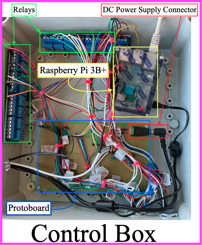
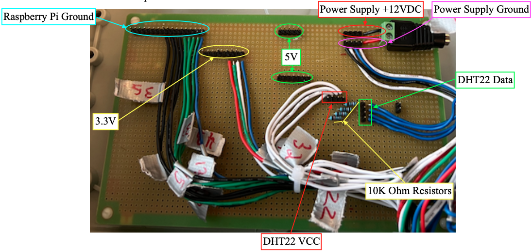
The contents of the control box include… The Raspberry Pi 3B+ for monitoring the environments and user requests, as well as control power delivery. Two 8-channel relay boards that allow the Raspberry Pi to control power delivery to each individual component. A custom through hole protoboard with GND, 5V, and 3.3V rail extensions for the Raspberry Pi. Additionally, the protoboard adds a 12V and GND rail for the 12V power supply needed for the solenoid valves and individual power and data connections bridged by a 10K ohm resistor for each of the 4 DHT22 sensors.
Protoboard Layout:
Display & UI:
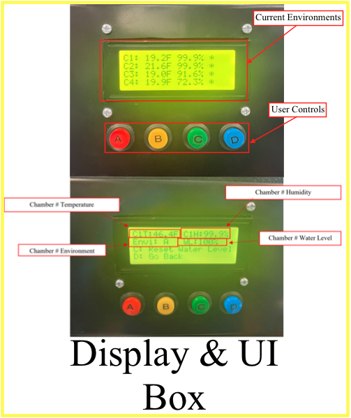
The UI box consists of an LCD to display environment data to the user and make the system easier to operate, and 4 buttons to allow users to navigate and make changes as necessary. The LCD can display temperature, humidity, indicate low water levels, and current environment preset for each chamber.
Cold Air Hub:

The Cold Air Hub distributes the cold air to the appropriate chamber. To accomplish this the Sustainable Fridge uses 4 solenoid valves to route cold air to the appropriate chamber. Cold air hoses then provide a path to the designated chamber.
Chamber Contents:
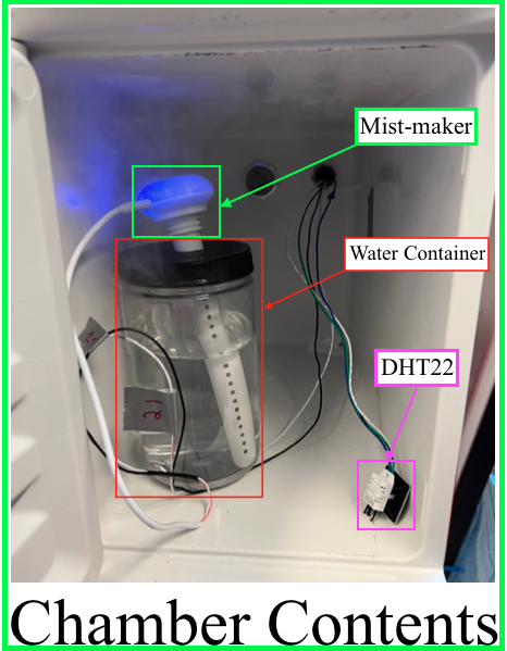
Each chamber in the chamber cluster is identical and houses the same three components a Mist-maker for humidity adjustments, a water container to supply the mist-maker, and a DHT22 to monitor the conditions within the chamber.
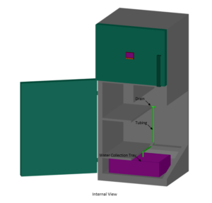
Humidity Overflow Reservoir, Drain, and Air Hose connections:
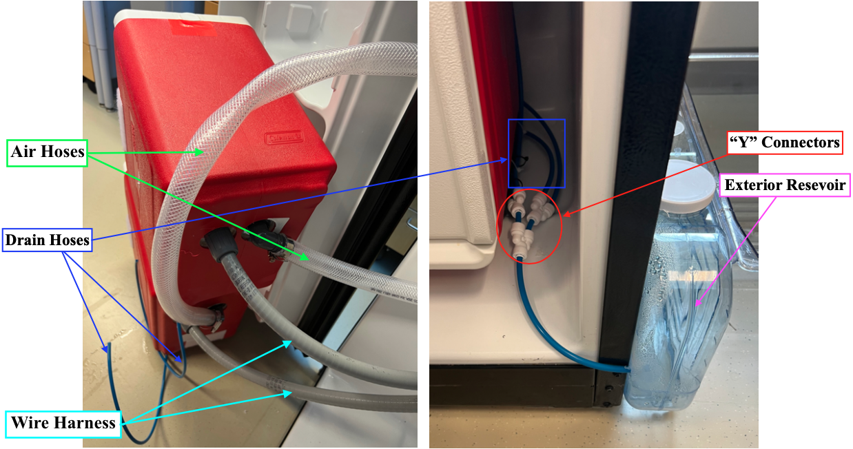
The Humidity Overflow Reservoir is feed by 4 blue hoes, one coming from each chamber. The 4 hoses are connected using “Y” connectors to leave only a single hose feeding the reservoir. The image above also shows the cold air hose and wiring harness that runs to each chamber.
Approximate build progression:
-

- 1) Experimenting with sensor setups
-

- 2) Successful setup 1/2
-

- 3) Successful setup 2/2
-

- 4) Modifying coolers to accept an air hose, wire harness, and drain hose
-

- 5) Building the cold air hub
-

- 6) Mounting the cold air hub
-

- 7) Connecting hoses and running the main wire harness through the cold air hub
-

- 8) Adding extra support to the cold air hub
-

- 9) Building the control box
-

- 10) Connect and mount all components to the fridge
-

- 11) Adjusting the fit and finish of the added components
-

- 12) Achieved proper door clearance
-

- 13) Experimenting with cold air delivery
-

- 14) Best cold air delivery method (At this point the chambers could reach temps just under 40 F)
-

- 15) Locate stock cold controller(silver box in front) and defrost timer(white plastic component in back)
-

- 16) Disconnect both modules
-

- 17) Replacing stock modules (Defrost timer drops in directly in the original defrost timer location)
-

- 18) Universal after market components are fully adjustable. Allow the fridge to run longer before stopping to defrost.
-

- 19) Run cold controller terminals into the refrigerator controls compartment (Original cold controller can stay in it’s original location, but disconnected)
-

- 20) Over night results, temps dropped from high 30s F to temps in the teens F.
-

- 21) Close control compartment, and mount new cold controller
Software Design
Flow chart for user interface navigation:
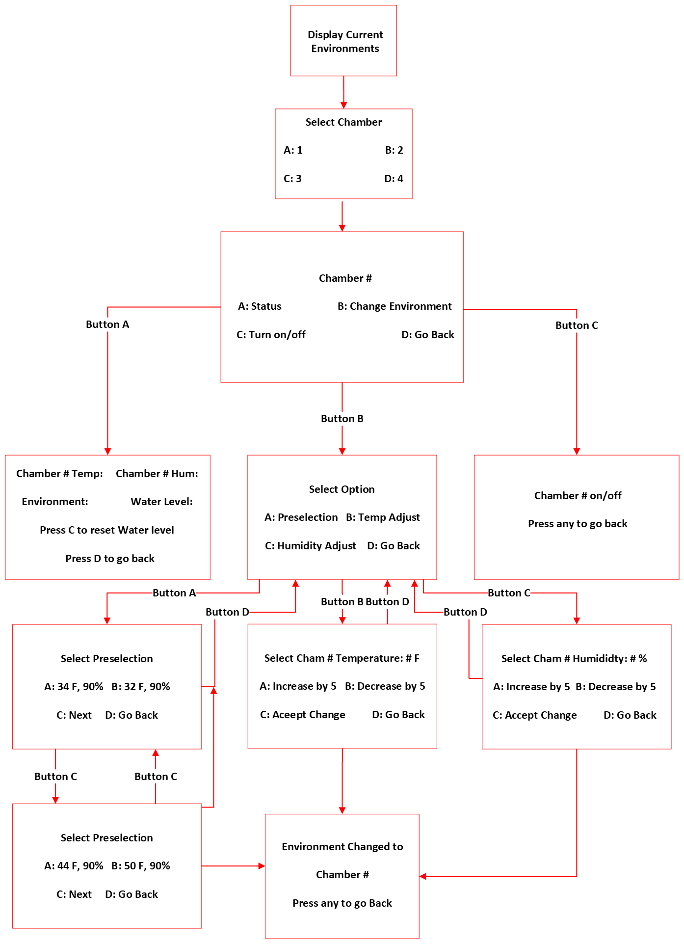
This flow chart illustrates the various options available to the user while interacting with the Sustainable Fridge user interface.
Diagram for creating a chamber list in the code:
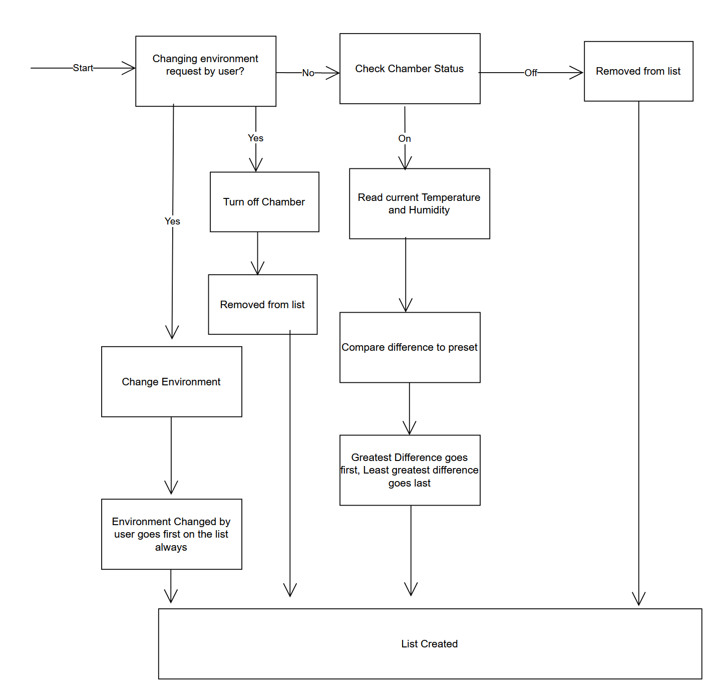
Flow chart representation of the program used to populate a list with the order in which chambers will be serviced. Priority is determined based on which chamber is farthest from its recommended environment and user inputs, with user request always taking priority.
Hardware Design
Updated Circuit Diagram

The circuit diagram was updated to use only a single Raspberry Pi since the 40 pin GPIO header has enough pins available to cover the project’s needs. This was achieved by using an I2C LCD driver to cut down on the necessary GPIO pins needed for the LCD.
Initial Design Plans & Prototyping (ECE 492)
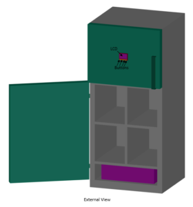
CAD of the Fridge:
Initial Pspice Diagram:

Recommend Food Groups to Test

These are the proposed produce groupings based on produce temperature preference, humidity preference, and ethylene production and sensitivity.